28
June3D modelling vs photomontage: Which does your project need?
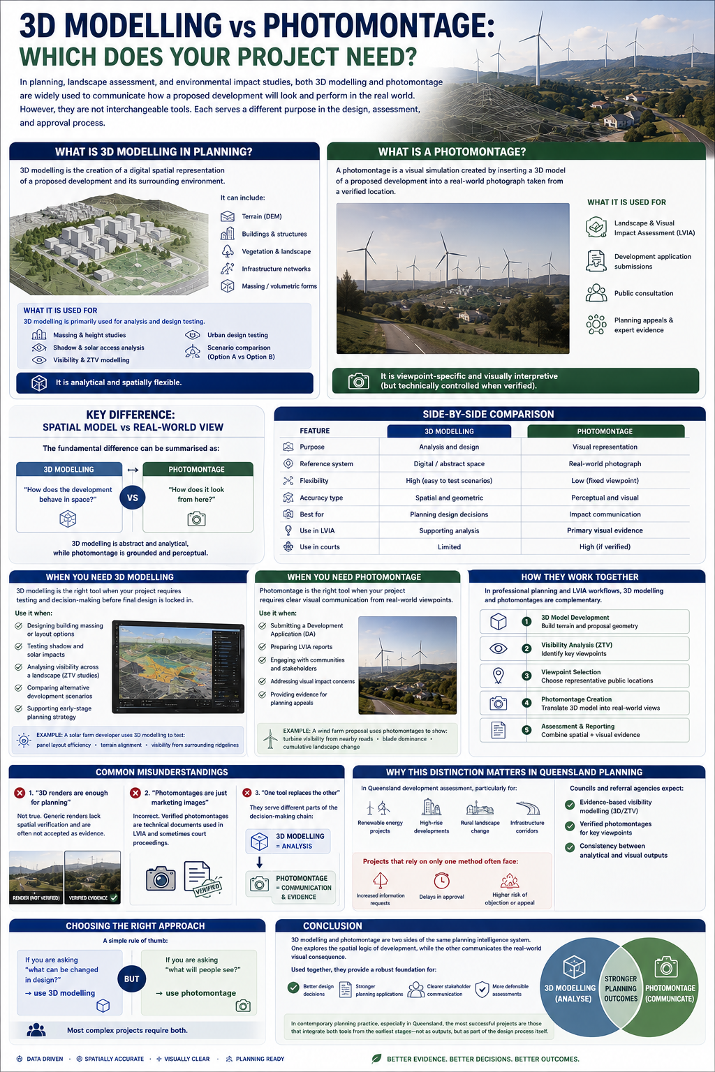
In planning, landscape assessment, and environmental impact studies, both 3D modelling and photomontage are widely used to communicate how a proposed development will look and perform in the real world. However, they are not interchangeable tools.
Each serves a different purpose in the design, assessment, and approval process—especially in Queensland development applications, infrastructure projects, and renewable energy proposals.
Understanding the difference is key to choosing the right method for your project.
What is 3D Modelling in Planning?
3D modelling is the creation of a digital spatial representation of a proposed development and its surrounding environment.
It is typically built using CAD, BIM, or GIS-integrated software and can include:
- Terrain (digital elevation models)
- Buildings and structures
- Vegetation and landscape elements
- Infrastructure networks
- Massing and volumetric forms
What it is used for:
3D modelling is primarily used for analysis and design testing, including:
- Massing and height studies
- Shadow and solar access analysis
- Visibility and Zone of Theoretical Visibility (ZTV) modelling
- Urban design testing
- Scenario comparison (Option A vs Option B)
It is analytical and spatially flexible.
What is a Photomontage?
A photomontage is a visual simulation created by inserting a 3D model of a proposed development into a real-world photograph taken from a verified location.
Unlike 3D modelling, it is anchored in a specific viewpoint in the real landscape.
What it is used for:
Photomontages are primarily used for visual communication and impact assessment, including:
- Landscape and Visual Impact Assessment (LVIA)
- Development application submissions
- Public consultation
- Planning appeals and expert evidence
It is viewpoint-specific and visually interpretive (but technically controlled when verified).
Key Difference: Spatial Model vs Real-World View
The fundamental difference can be summarised as:
| Tool | Core Question Answered |
|---|---|
| 3D Modelling | “How does the development behave in space?” |
| Photomontage | “How does it look from here?” |
3D modelling is abstract and analytical, while photomontage is grounded and perceptual.
Side-by-Side Comparison
| Feature | 3D Modelling | Photomontage |
|---|---|---|
| Purpose | Analysis and design | Visual representation |
| Reference system | Digital/abstract space | Real-world photograph |
| Flexibility | High (easy to test scenarios) | Low (fixed viewpoint) |
| Accuracy type | Spatial and geometric | Perceptual and visual |
| Best for | Planning design decisions | Impact communication |
| Use in LVIA | Supporting analysis | Primary visual evidence |
| Use in courts | Limited | High (if verified) |
When You Need 3D Modelling
3D modelling is the right tool when your project requires testing and decision-making before final design is locked in.
Use it when:
- Designing building massing or layout options
- Testing shadow and solar impacts
- Analysing visibility across a landscape (ZTV studies)
- Comparing alternative development scenarios
- Supporting early-stage planning strategy
Example:
A solar farm developer uses 3D modelling to test:
- Panel layout efficiency
- Terrain alignment
- Visibility from surrounding ridgelines
When You Need Photomontage
Photomontage is the right tool when your project requires clear visual communication from real-world viewpoints.
Use it when:
- Submitting a Development Application (DA)
- Preparing LVIA reports
- Engaging with communities and stakeholders
- Addressing visual impact concerns
- Providing evidence for planning appeals
Example:
A wind farm proposal uses photomontages to show:
- Turbine visibility from nearby roads
- Blade dominance in key viewpoints
- Cumulative landscape change
How They Work Together
In professional planning and LVIA workflows, 3D modelling and photomontages are not competing tools—they are complementary.
A typical workflow looks like this:
- 3D Model Development
- Build terrain and proposal geometry
- Visibility Analysis (ZTV)
- Identify key viewpoints
- Viewpoint Selection
- Choose representative public locations
- Photomontage Creation
- Translate 3D model into real-world views
- Assessment & Reporting
- Combine spatial + visual evidence
This integrated approach strengthens both technical and visual credibility.
Common Misunderstandings
1. “3D renders are enough for planning”
Not true. Generic renders lack spatial verification and are often not accepted as evidence.
2. “Photomontages are just marketing images”
Incorrect. Verified photomontages are technical documents used in LVIA and sometimes court proceedings.
3. “One tool replaces the other”
They serve different parts of the decision-making chain:
- 3D modelling = analysis
- Photomontage = communication and evidence
Why This Distinction Matters in Queensland Planning
In Queensland development assessment, particularly for:
- Renewable energy projects
- High-rise developments
- Rural landscape change
- Infrastructure corridors
Councils and referral agencies expect:
- Evidence-based visibility modelling (3D/ZTV)
- Verified photomontages for key viewpoints
- Consistency between analytical and visual outputs
Projects that rely on only one method often face:
- Increased information requests
- Delays in approval
- Higher risk of objection or appeal
Choosing the Right Approach
A simple rule of thumb:
- If you are asking “what can be changed in design?” → use 3D modelling
- If you are asking “what will people see?” → use photomontage
Most complex projects require both.
Conclusion
3D modelling and photomontage are two sides of the same planning intelligence system. One explores the spatial logic of development, while the other communicates the real-world visual consequence.
Used together, they provide a robust foundation for:
- Better design decisions
- Stronger planning applications
- Clearer stakeholder communication
- More defensible impact assessments
In contemporary planning practice, especially in Queensland, the most successful projects are those that integrate both tools from the earliest stages—not as outputs, but as part of the design process itself.